Modelling Notes:
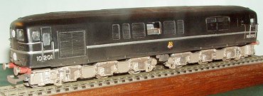
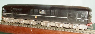
Silver Fox Bulleid 10201/2/3 Diesel Electric
Locomotive Body Kit
by Graham R 'Muz' Muspratt
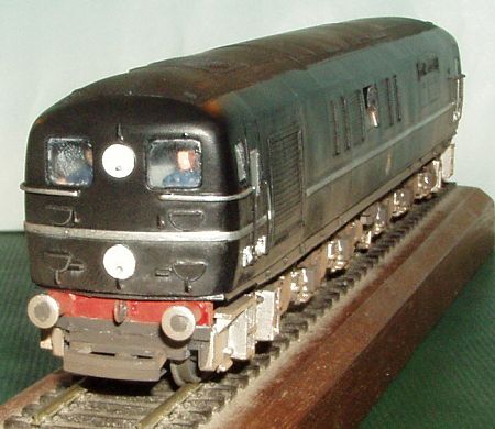 This kit of the Bulleid 1CoCo1 Diesel Locomotives is designed to fit on either a modified Lima Class 40 class chassis or a modified Mainline/Bachmann Class 45 (power bogie type) chassis. A basic A4 instruction leaflet is supplied with one side giving instructions for fitting the Lima chassis and the other side the mainline chassis. Kit, as supplied:
 Chassis modifications: The metal weights (a stack of 2mm thick metal plates) inside the chassis also need to be shortened and glued back into the chassis in accordance with the instructions. I chose to move away from the instructions here slightly, the metal weights are located on two plastic pegs and held in place with screws, I decided to shorten the weights and drill a new hole for the locating pegs and at the same time drill a 2.5mm hole through the weights which I would later use for the body fixing screw. This fixing screw hole lines up with the gap in the Mainline chassis left after the underside fuel tanks were removed. I glued the bottom weight into position fixing the two halves of the chassis back together. The rest of the shortened and re-drilled weights were then held in place using the original screws into the locating pegs. The Mainline Class 45 chassis has steps moulded onto the chassis, whilst at the No. 2 end these just about line up the step board for the small access panel they need to be removed at the No. 1 end with very careful surgery. I made new steps to locate under the cab doors (thankfully only one each end) from Plasticard referring to prototype photographs. The steps are quite chunky fabrications on the prototype and it's a shame that these could not have been included as castings by Silver Fox. Cast resin buffer beam and buffer mouldings are provided to be glued to the front of each bogie. I removed the moulded coupling hook. The tension lock couplings on the Mainline bogies are screwed to a tab projecting from the front. These look unsightly and project too far forward on 10201-3. I therefore cut these off and mounted the couplings further back by carefully drilling a new position for the self tapping screw and gluing as well. Eventually these will be replaced on my model by Dingham couplings anyway. When I do so I will add the details to the underside of the buffer beam as per the prototype. 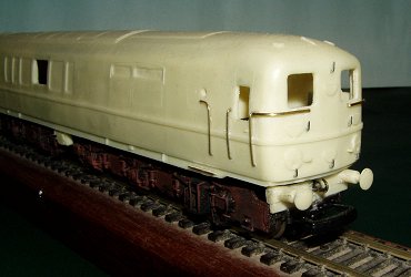
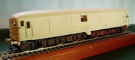
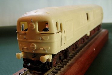 Body modifications: The Silver Fox body moulding missed the two hand rails located further back from the cab doors at the No. 2 end of the loco to give access the small opening panel located there, on one side this is a short vertical straight handrail but on the other side it's curved at the top just below a small circular viewing window. This window is also missing from the Silver Fox body and I simply drilled a 2mm hole by reference to photographs for positioning. The two shallow moulded step-boards located on the side frame under these two handrails (strange that Silver Fox moulded the step boards at these points but did not include the handrails above or the small circular window) were also removed and replaced with 15 thou brass. Lamp irons (Bambi staples) were fitted. The body already has the route indicator discs moulded in place. The No. 1 end has a Southern headcode for Waterloo - Exeter whilst the No. 2 end shows an express passenger headcode. These are in fact quite nicely moulded and I resisted the temptation to remove from the body and replace them with brass discs from Roxey Mouldings. Whilst apertures are already open for the front and side cab windows and flush glazing provided for them there are two large opening side windows (open by sliding downwards) in the middle of each side. These are moulded on the Silver Fox bodyside as just a body side panel. In nearly all the photographs that I have seen of these engines these side windows were open or partially open. I therefore drilled out the opening and have fitted windows and frames in the open position on each side. Due to these windows being open I also raided to the scrap box to make up something that represents a large engine block and generator to fit inside the body at this point. Chassis to Body Fixing: To locate the chassis at the correct height within the body I glued a piece of plastic 'I' beam down the inside of each side for the chassis top to rest against. (There is a moulded recess down each side higher up the body side which I assume to be correct for the Lima chassis perhaps.) The Silver Fox instructions suggest gluing the chassis into the body with a small amount of contact adhesive. As I did not like the idea of this I soldered an 8 BA nut to a 20 thou brass plate which I then glued across the underside of the roof to line up with the hole that I had previously drilled in the metals weights in the middle of the chassis. A long 8BA screw cut to the correct length is used to hold the body in position Since fitting the chassis back to the body I have noticed that it leaves the bogie centres slightly further back from the front of the engine than they should be. If I had noticed this before I shortened the chassis I would have shortened each end first (from the extreme ends of the chassis) to get the bogie centres the correct distance from the ends before cutting and shortening the middle of the chassis. If I see another Mainline chassis going very cheap (after all I only need the chassis frame) I will be tempted to correct this in the future. 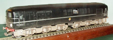 Overall: The cast components were on the whole clean although the rivet, panel, cab door and louvre detail is very fine and risks being lost under a coat of primer and top coat. I do feel that it is a shame that Silver Fox chose to mould on details such as hand rails etc, but with resin being quite a soft medium there are very easily removed with a sharp scalpel. I was also surprised that they missed the small circular viewing window and the handrails. The fact that Silver Fox suggested simplified the fitting of the Mainline chassis by just shortening it in the middle, which leaves the bogie centres incorrect, is also a minus point. I would also have liked to see a better method of fixing the body to the chassis, rather than simply suggesting lightly gluing the body to the chassis, perhaps a central cast boss on the underside of the roof to allow a fixing screw to be used would have been a simple solution. The instruction sheet was very simple and lacked any prototype backgrounds or history. General notes on working with cast resin: Prior to painting clean the resin body thoroughly and I then suggest the use of a plastic primer. I use an aerosol from Halfords. It is a common practice with white metal or brass kits, once a model body is washed prior to painting gently heat the body, in an oven, to ensure it is totally dry first and also to give a warm surface for the paint to adhere to. I must note here that extreme care must be taken with cast resign bodies with this practice otherwise warping could occur. |
 |
all photographs are copyright Graham R 'Muz' Muspratt.
return to model railway product reviews index
This page was last updated 8 February 2004
![]()