KR Models 4DD EMU
| A comprehensive review of the KR Models 4DD by Colin Duff, first published on the Southern Electric Group' website. All photographs © Colin Duff 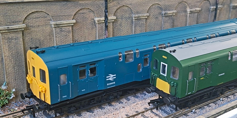
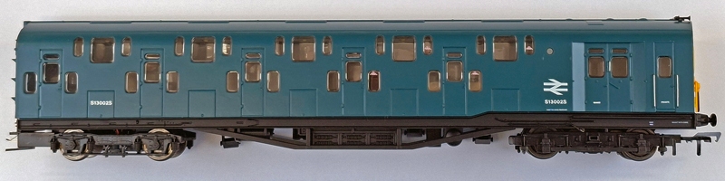
I ordered two. The BR green with small yellow warning panel version (which whilst not specified at the time of ordering comes with the odd white surround to the headcode windows, applied at Eastleigh during a re-paint, that it mercifully carried for only a short while) and a BR blue version. If modelling the Southern Electric system is a small niche of modelling, then producing a model of a class that only had two four car units, that only ran on a small number of routes, and mostly ran during the morning and evening peaks, is a micro-niche. It can be viewed as a courageous decision to produce as a model, but on the other hand the 4DDs have the cachet of being the only double deck train ever to run in Britain so far. (At this point an uber-pedant will point out that whilst always known as a double deck train arguably it is a bi-level as the compartments are interlaced, not stacked!) There is usually a market for models of unique or special trains. Reference materials I have consulted for this appraisal are:
Packaging: The only parts separately supplied to be fitted by the modeller are pair of dummy screw couplings and sheet of headcodes. Also supplied is an impressive twelve page A4 size booklet which contains an illustrated history of the 4DDs written by John Atkinson, information about preservation of the two remaining 4DD vehicles, and instructions for the model. However, right from the start doubts about poor attention to detail by K R Models are raised. The booklet (with two exceptions) insists on calling the 4DD's designer as Oliver Bullied (sic). Perhaps they can blame a spelling checker for this, but then you can usually add spellings to a custom dictionary, and ultimately such multiple mistakes ought to have been noticed and corrected. Not a perfect start then. Body:
The shape of the bodies is very good. The 4DDs have a flat body side, but with a very slight taper to the top (quoted as 1 inch taper in at the cornice), and this is credibly reproduced. Try putting a straight edge from floor to roof to notice this subtlety - even if not to precise sub-millimetre measurements. The curvature of the roof, when offered up to the Mike King drawing, does not quite match as the drawing has a slightly flatter curve, however the model looks more like in the photos, so I'll give it benefit of the doubt. The layout of the windows and doors is accurate. Major dimensions - length over bodies and length from front buffers to inner ends (DMBS cars), car width, car height, length between bogie centres, powered and unpowered bogie wheelbases, and the diameter of all wheels - are completely accurate. Widths and heights of the doors are correct. I did not check every single axle on both units, but wheel back-to-back measurements, where measured, were correct. Though some were very close to being under gauge. However, according to Mike King's drawings all windows on this model are consistently a fraction too small, approaching 1mm too narrow and too short. I did not notice this just looking at the model, excepting the windows to the upper compartments which consequently do not appear to go high enough into the roof. Some modellers have expressed an opinion, which occurred to me as well, that we look down on a model whereas the prototype is usually viewed from platform and ground level, so the model will look different. Indeed, photos I took of my model from "ground level" looked better than those taken from an elevated position. Southern Electrics Volume 2 1948-1972/Kevin Derrick/Strathwood, specifically pages 32 and 33, has large clear pictures of the roofs of 4001 and 4002. Comparing these pictures to the model indeed suggests that the model's windows do not go quite high enough into the roof. I measured the height of the upper compartment windows on the 2D drawing and then cut a piece of paper to this length, offering it up to the model's window and wrapping it around the curve. The tops of these windows were found to be about 1mm too low. I also think the prismatic effect of the flush glazing is particularly noticeable on a curved window and it does not help it look right. The positions of the rain strips were also measured by the same method and also found to be about 1mm too low.
The rounded rectangular vents to the upper compartments on the model are 16mm long but should only be about 8mm long. This over-length is extremely obvious. There are no periscopes on my two models. This is probably accurate for their period, but I have been unable to find a picture of 4002's DMBS roof in its green sywp era to confirm the accuracy of this version. Mike King's drawings for the roof details are annotated as "typical roof conduit layouts", so maybe not totally accurate. The drawings are significantly different to the model. The roof photos in Southern Electrics Volume 2 1948-1972 are again helpful here. The details of both DMBS and TS are clear enough to judge that Mike King's drawings, whilst not totally accurate, are more accurate than the model. I will not go into detail about the specific inaccuracies in the number of conduits and their layouts, suffice it to say that the model is significantly different to photographs in places. Some roof photos show there to be a fourth circular vent above the guard's compartments, lower down the roof, not along the centre line as the other three. However other photos show the roofs without. I suspect that at some time towards the end of the units' lives they were removed, but according to pictures later than when the periscopes were removed. Neither of my two models have these lower vents. This paragraph has been revised from the original version The coaches are coupled together with electrically conducting couplings which are handed. The handed couplings unfortunately result in the wrong ends of the trailers being coupled to the power cars. Mike King's drawings call the cabs end "A", inner ends to the DMBS and one end of each TS "B" and the other inner ends of the TS cars "C". The correct unit formation is A-B + B-C + C-B + B-A. However, the model, as produced, is A-B + C-B + B-C + B-A. Intially I thought the trailers may have been assembled incorrectly? However, it was then something I had missed was pointed out to me, namely that one end of the chassis of each trailer has a footstep and continuation of a conduit moulded onto it, which align with the coach end above. The following has been tried successfully and the trailer bodies can easily be reversed on their chassis, however, the moulded detail on the chassis ends will have to be removed and replaced with a step and conduit made of Plastikard and wire respectively on the other ends. The bodies are easy to remove (follow instructions in the booklet) and replace, just be careful to avoid damaging detail on the underframe whilst handling.
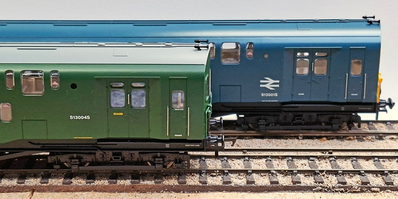
Details on the inner ends are different to those on Mike King's Drawings. As with the roof conduits I am not listing specific differences, the overview being the B end only has minor discrepancies but the C ends are significantly different, particularly in respect of two equipment boxes not being portrayed. Unfortunately, I have yet to find any pictures of the inner ends to confirm the reality. The cab ends are modelled without windscreen wipers, which is rather obvious. It makes the models' cab ends look like pictures I have of the DMBS at Sellindge during storage and restoration! Paint is very well applied and the printing of numbers and lettering razor sharp. Every bit as good as on Hornby and Bachmann models. Finish is a matter of personal opinion, but I am happy with the satin finish. The perception of colour is complex and differs between individuals, the production and reproduction of colour is subject to a number of physical factors. If you have read any of my previous reviews you will know I never declare a colour correct or incorrect, merely credible or not. I think the BR blue finish is credible. However, I am not at all happy with the shade of green, which I do not consider credible. It is a pleasing shade of green and would look credible on a model of series 1 & 2 Land Rovers, as I think it is in the region of mid-bronze green. Even allowing for any scale compression of colour it does not match any shade of green used by the Southern Region when compared to HMRS colour-controlled colour swatches. It is definitely not BR Green No.11, which it should be after 1956, nor is it the earlier post nationalisation "version" of Southern malachite (this is how it is described in various accounts) applied to all regions' multiple units until 1956. One thing I immediately noticed when I unwrapped the coaches, and subsequently on publicity photos of the versions I do not have, is that coach numbers on both DMBS and TS cars of both units are not always in the correct quantity or positions, and on the green unit car numbers are white, not yellow. Each side of the DMBS cars has coach numbers at each end, so four in total. The TS cars have the correct quantity of car numbers but on either side at the same end. I cannot find photographic evidence nor documentation to support any of this. These are pretty gross errors given that the positions and colours of BR coach numbering are well documented and photographed.
Some of the compartment windows have the recognisable red no smoking triangle markings, not always added to RTR coaches, so well done K R Models for this. The ratio of smoking to not no smoking accommodation changed over time so reference to the Appendices of the Carriage Working Notices of the time appropriate to each version will be required to establish veracity. My two models had the same amount of no smoking accommodation and in the same compartments. However, the triangular markings fill the entire width of the inset of the flush glazing. This is probably a combination of the markings being too large and the windows too narrow. Also the no smoking triangles have only been put onto one window on each side of the compartment whereas I recall on, say a 4Sub unit, they appeared either side of the door on both sides of the coach. Finally for this section, as delivered some bodies were not fully pushed home and engaged to lugs on the chassis. Interiors and Lighting:
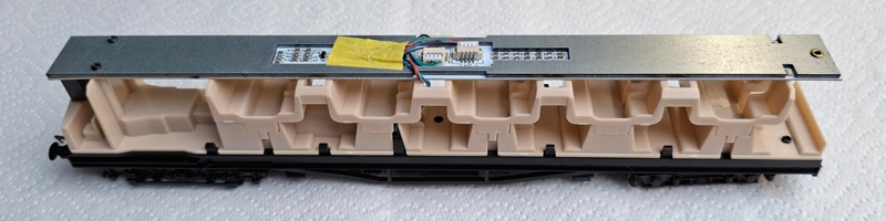
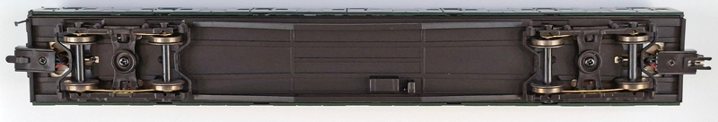
Atop the interior moulding is a LED lighting bar, from which lighted headcode boxes are attached underneath at the driving cab ends of the DMBS interiors. Unlike on Bachmann Southern EMUs heacode illumination is not red on the rear cab. Good! I prefer the rear headcode to be white and to rely on red blank blinds so you do not get a numerical headcode incorrectly illuminated red in one direction. When using DCC the headcode, cab and compartment lights can be separately switched. The instructions incorrectly call the headcode a number plate. Uniquely the cab lights are directional and light when the train is stopped on DCC. Unlike on other manufacturers multiple units there are no DIP switches to control lighting when using DC. In my opinion the compartment lighting is too bright, showing up the basic interior, and a tad too white for its era. Headcode box lighting is also perhaps a bit too white but I have not yet applied the headcode stickers. The instructions do not mention applying these stickers. I assume they are intended to be applied on the outside of the headcode window, as on Hornby Southern EMUs, but I have never liked the look of this as the headcode blinds they are representing are actually behind glass. However, with the headcode boxes being attached to the lighting bar I am wondering if the stickers can be applied to the front of the box and thus appear behind the headcode window. I will experiment with this when I get more time. Headcodes supplied are 55, 66, 75, 76 & 86, but unfortunately there are no white and red blanks, which is a shame. These headcodes are correct for Charing Cross or Cannon Street to Gravesend routes around the lifetime of these trains. Chassis, Bogies Underframe and Drive Mechanism: Like the real trains there are powered motor bogies under the cabs at each end. However, only one DCC decoder is required, of which more later. Excellent! There is a small motor and flywheel driving both axles of the motor bogie via a drive shaft and short gear tower. This assembly is placed under a raised floor in the guards' compartment and under the first upper compartment, so is not visible. Very good!
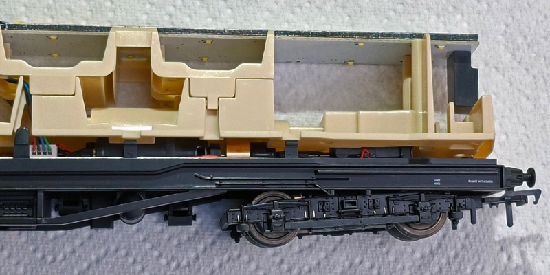
Remarkably, and commendably, there is all-wheel pickup on all four cars. This is an amazing 32 wheel pickup! These feed a track power busbar into the DCC decoder socket. The DCC decoder socket then feeds power to both motors via motor power busbars. This means that one DMBS (the odd numbered power car) can run alone as, in effect, a locomotive, but the other (even numbered) power car needs to be coupled to the first, either directly or via the trailers, to run. This is all good stuff! The unit is coupled together using 8 pin electrically conducting handed couplers which push together and take apart easier than most. Hurrah! These require pushing fully home to a quiet "click". There are guides to assist pushing couplers together and the underside of these guides have corresponding circular lugs and circular notches. These look like they are for locking the two couplers together, except when fully pushed home the lugs and notches do not meet! I have noticed that despite pushing the couplers fully home there is a tendency to slightly pull apart when running, but so far, with very limited running (read later), not enough to lose electrical continuity or completely uncouple. The power busbars account for four of the eight wires along the cars, the other four wires I suspect somehow control the three lighting circuits and connect loudspeakers in both power cars in parallel. Out of the box I found one of my even numbered power cars (the green version) was electrically dead despite remaking the couplings between all cars several times. I took the body off and had a peek at the mechanism and electrics, but could not see anything wrong. To test I wanted to try powering the motor directly, but could not get to the motor terminals without taking it more apart and removing wiring insulation. For the want of something to do I remade the two 4pin JST plug connections on the upper circuit board, not expecting it to make any difference. But after I put the body back on and coupled it to the other power car it sprung into life! The bogies on this model are modelled to OO gauge, not 4mm scale, width. So, the shoe beams align with conductor rail on 16.5mm gauge track (but without contacting correct height conductor rail), unlike the vast majority of other Southern Electric models where they are positioned outside of the conductor rail. This will make converting them to EM or S4 difficult. Stepboards (where fitted on the prototype) on unpowered bogies are not reproduced at all. As on the real trains between cars there are single centrally placed buffers on the end of one car buffering to a rubbing plate on the adjacent car. The modelled central buffers between cars are sprung. However, despite in reality, and on a diagram in the instructions, there is no central buffer between the two trailer cars, only between the driving cars and trailers. The weight of power cars is approximately 270g and trailers approximately 250g, one would think good for traction and staying on the track.
Running the model: Such derailments have happened before. Like when Bachmann introduced their new Mk1s with close coupling mechanism. This mechanism's swing arm had a small moulding pip that was rubbing on the centreing spring, causing resistance and binding, thus causing adverse lateral "vector forces". To cast my degree in Physics aside, basically - tug a coach at an angle away from the direction of travel and it will try to tug it off the track! For any coupling to work reliably it has to be able to transfer the force completely in a straight line between the couplers' pivot points, which are on a close coupling mechanism are moveable. The solution with the Bachman Mk1s was to take the mechanism apart to file off the pip, but I found just removing the spring worked just as well and requires no disassembly. Other similar close coupling mechanisms - like the Keen system - do not have the springs and in my limited experience work well. Additionally the bogies on the 4DD can touch the swing arm of the mechanism when pivoting, particularly on tighter radii. The bogies do not rotate particularly freely and the cars are so close coupled that the central buffers, where fitted, are actually buffing. None of this can help as they will contribute adverse vector forces. I have not yet had time to experiment with potential remedies, but lubricating the close coupling mechanisms will be a good start, and then look at the bogie cross-frame member touching the swing arm (perhaps remove it?), followed by preventing the central buffers causing friction. Note all these problems occur on both of my models. So it is more than a single rogue model. Because of the regular derailments I have so far been unable to assess how powerful this model is. Can it, as I have seen in a You Tube video, haul a trailing load (like an unpowered 4DD made from a kit)? My layout is level so I have also been unable to assess how it copes with gradients.
Conclusion: I have assisted with researching and developing Southern Electric RTR models so I do not underestimate the challenges of the task. There are an enormous number of dimensions and details to verify and numerous issues to resolve, then there is the need to reproduce them as accurately as possible in a small scale. Compromises are required, not only for financial viability reasons but also because of the properties of materials used. Then there is the poor to non-existent version control of drawings when working with factories in China. During the iterative process changes made in previous drawings can become undone, meaning every detail needs to be checked and rechecked meticulously. Ironically photos and drawings in the supplied booklet clearly illustrate inaccuracies on the model, you do not need to spend months researching in obscure libraries. My reference sources came straight off my bookshelf. It should not cost more, and take longer, to get well documented and photographed details correct. I know the occasional mistake can slip through, no matter how careful you are, but the conclusion that these models suffer from poor attention to detail is inescapable. The result is that even with using modern design tools, modern materials, and modern production processes, unfortunately this is a model with the overall fidelity to the prototype train of a model designed and produced 30 years earlier. Also its propensity to derail is not good. Other manufacturers can produce more accurate and better running models for the same price. One should not have to do so much work to correct a model. Some modellers have expressed an opinion that any RTR 4DD model is better than none, but I think in 2025 we deserve better. Sadly, this could have been a definitive model, so what a missed opportunity!
|
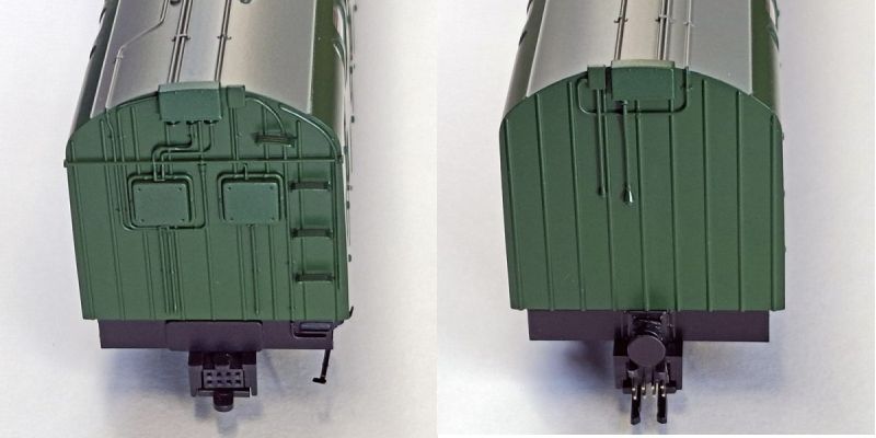
 A pair of cab fronts, both later versions. Note the obvious absence of the windscreen wipers.


All photographs are copyright
return to model railway product review index
This page was revised 30 December 2025
![]()