Modelling Notes:
Golden Arrow Productions W Class Body Kit
by Graham R 'Muz' Muspratt
For information on the prototype please visit our W Class section. |
| This kit is designed to fit on a slightly modified
Bachmann N class chassis (see notes below). A very basic single-sided A5
instruction leaflet is supplied which gives details, but no diagrams, on
fitting the chassis (basic method without other modification) and then suggests
that prototype photographs are used to identify other body detailing.
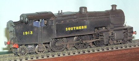
The Kit, as supplied:
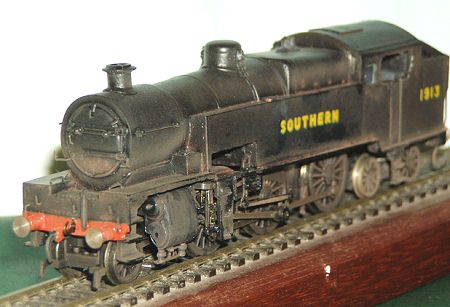
The N class chassis is fitted by carefully removing the tender dragbox area at the rear of the chassis (ensuring that the two rivets which are part of the current collection systems are not damaged) and shortening the front by a few millimetres. The motion components and the cylinders on the N class, however, are not quite correct for the W class.
To be fair to Golden Arrow the instructions supplied do mention the incorrect shape of the cylinders and suggest either filing to shape or removing the cylinders from the bracket and re fixing at the correct angle. They have obviously not tried the latter as the motion assembly would not then work! Chassis modifications:Cylinder Block - The front mouldings for the valve chest were then re-affixed. The rear valve chest mouldings were re-affixed once the brackets to support the pivot of the radius bar were removed. Before re-assembling the valve gear I simply re-drilled the piston rod hole in each cylinder to ensure that no Milliput® impeded the movement of the rod. (Note from Colin Duff: an alternative would be to purchase W class cylinders as spares from South Eastern Finecast, though we have not yet devised instructions of how to do this particular modification.) Radius Arm - Support bracket - The vertical part of the bracket was made with a U shape piece of 10 thou brass. The rear of this was drilled to accept the pin on the back of the combination lever. I soldered these vertical brackets to the horizontal bracket, both of which were drilled to take a short length of 0.5mm brass rod to strengthen the joint and act as a representation of the pivot rod on the outside. Rear Bogie - Rear of Bachmann chassis- |
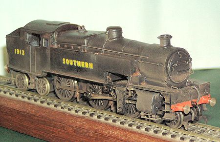 |
| Body modifications: The body that I received had a number of small cast blemishes which required a small out of care and filling at the paint stage and a couple of larger problems such as a slightly warped tank side and the fact that the running plate from the front of the cab, under the tanks up to the turn up by the cylinders was of varying thickness and broken under the tank cut out on one side and was easily damaged when removing the cast temporary strengthening ribs under the tank cut out. (Note from Colin Duff: these faults are not exclusive to the casting Graham Muz bought because several other SREmG members have castings with identical problems.) The warped tank side was corrected by gently heating in a oven with the tank sides gently clamped between two flat metal bars (my bending bars, in fact), once warm slightly tightening them until I was happy with the flatness of the tank side and then letting it cool gently. Once cold the resin body held its new shape. To correct the running plate I decided to remove the damaged section completely and replaced it with a length of 30 thou x ¼" brass. This needs to be drilled and filed to allow the expansion link (bearing in mind that this oscillates) and lifting links to protrude through. This once glued into position also adds strength to the base of the tank sides following their straightening in the oven. I also fitted to the brass running plate turned brass splashers for the front driving wheels that can be seen through the tank cut out. A small length of ¾" copper tube was glued in place in line with the tank cut outs to represent the underside of the boiler and then the surrounding areas in filled with Milliput® to form the underside of the tanks etc. This also has the added advantage of providing extra weight at the front end. To add additional weight at the rear I glued lead in the space under the coalbunker. Brass sprung buffers (Gibson), hand rail knobs and rails (refer to prototype photographs as some had additional grab handles located on the tank sides above the middle set of steps), lamp irons (Bambi staples), brass safety valves (Westwood) and sniffing vales (if correct to your period, not in my case), front, middle and rear cap steps, bunker steps, vacuum and steam heating hoses were added to complete the body. Note: Numbers (3)1911 to (3)1915 were built at Eastleigh and were right hand drive and originally painted in black with dark green lining until approx. 1931 then unlined black prevailed as per the rest of the class. The remaining ten were built at Ashford and were left hand drive. The main visible external difference between the versions was the pipe running from the cab along the side of the boiler to the smokebox which is only on the drivers side. Overall: I do feel that the instructions lacked detail and would rather have had some diagrams showing handrail positions, as well as greater detail on where to cut the chassis, etc. Some background on the prototype would also have been welcome. General notes on working with cast resin: Prior to painting clean the resin body thoroughly and I then suggest the use of a plastic primer. I use an aerosol from Halfords. It is a common practice with white metal or brass kits, once a model body is washed prior to painting gently heat the body, in an oven, to ensure it is totally dry first and also to give a warm surface for the paint to adhere to. I must note here that extreme care must be taken with cast resign bodies with this practice otherwise warping could occur. |
 |
all photographs are copyright.
return to model railway product reviews index
This page was created 3 January 2004
![]()